measure the shaft across the diameter only not where the key way is
so 90 degrees to your picture
Printable View
measure the shaft across the diameter only not where the key way is
so 90 degrees to your picture
There are many different sizes. If you're going to make knives, I suggest you buy a pair of calipers.
they're cheap, and you will be able to tell exactly how thick or wide a piece of metal is.
Sometimes the difference in axle sizes is minute, and with a simple ruler, you're not going to be able to tell.
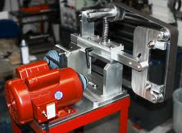
I have a caliper. it measures the shaft .875 . 7/8ths of an inch. so ,according to the KMG plans I go buy I need to buy a shaft that is 7/8ths inches wide. but on there parts list , it looks like he purchased a 2 foot long shaft. I don't think there is a need for such a long shaft. so the way I figure is once side of shaft has drive wheel, then through the pillow block bearings. then a pully on the other end. the pully has a small belt going to the pully on the motor. I suppose I could just line up the motor behind and run the drive wheel right on the motor ? but that would elongate the entire unit. Attachment 199133
you will see in the attached pic what I am talking about . I could 1...either use the pully system to drive the wheel. ? Or is there a way to just extend the shaft of the motor? buy another shaft and couple them together ? suggestions ? this is all new to me . thanks, David
The drive wheels for my grinders are mounted directly on the motor.
The motors are powered by a VFD so pulleys are not necessary.
Attachment 199137
so , do you mean like the attached. just mount the motor behind he structure ? I guess since the kmg plans I am looking at don't have it that way but seems easy enough ?
Also, I am getting ready to purchase the tooling arm . how long does it need to be ? if I have 2 , is 18 inches each enough. I am going for a round contact wheel and a flat platen , so it would be nice to have a tooling arm for both .
If you have a VFD, mount the motor just like your picture in post #45. If you don't have a VFD, mount the motor like post #43. You need to be able to control you speed.
Yes I have a vfd. Thanks
This depends on the size and placement of the drive and tracking wheels, in relation to the receiver tube, and the size of your smallest contact wheel. I use a 2" drive wheel and often a 2" contact wheel. The 1-1/4" tool arm was sold by the foot. It appeared that I could get by with 20" so I ordered 2 feet. I saw no reason to cut 4" off so I left it at 24" now I'm glad it's a little long because there is better support as well as the possibility of shortening it if I ever needed to change any of the holes in the working end.Quote:
Originally Posted by drmccubx
The confusion may be that the KMG grinders all have the pulley system regardless of whether they are single speed or VFD because the two models are identical but for the VFD controller.Quote:
Originally Posted by Bruno
yup . that's it . I will just mount the drive wheel to the motor and place the motor where it needs to be to line up with the other wheels when the time comes.
progress. well, next step is scribe out the final lines that need to be cut . and mark where the holes that will be tapped are going to be . my cousin has a friend who works at a machine shop and volunteered to do the rest of the cutting, tapping and dying and what not , so that's awesome. tomorrow at some point I mark out all the metal with detailed explanation's of what I want done. then send it to my nephew who will give it to his bud then I wait. when I get it back , I weld it all together. meanwhile I buy handles for arm and tracking and so on. cant wait .
Ok, so an update with questions. I have the motor, vfd, metal mostly cut , just a couple cuts remaining. what I need to know is this . what size compression spring ? my build will be much like a KMG grinder. "spring under tension arm. Hoping to make progress within the next week.
Nothing too flimsy I'd say. Take a look at the KMG ones, and then pick something close.
I used a valve spring along with it's end caps. The throw on the spring is very short but it is a strong spring and works perfectly. I located it very close on the arm to where the tracking pulley is located.Quote:
Originally Posted by drmccubx
Attachment 205257
I am going with a Gas spring strut tat I intend to hide inside a vertical tensioning post, and all the info I have founds has a general consensus of about a 15kg/33lb (150n) strut so I would assume that the spring would be a similar rating
I ordered this for mine. 12" long with 4" travel
150N Force 300 X 18mm Lift Support Shock Strut ARM GAS Spring ROD FOR CAR | eBay
Keep in mind that the tension in a spring is a linear function of its compression, so you'll have to some fine tuning to make sure that when you are using it, the compression is such that that is the specific tension you'll end up with.
Attachment 205683Attachment 205684Attachment 205685Attachment 205686Attachment 205687
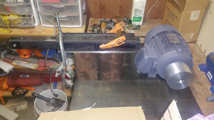
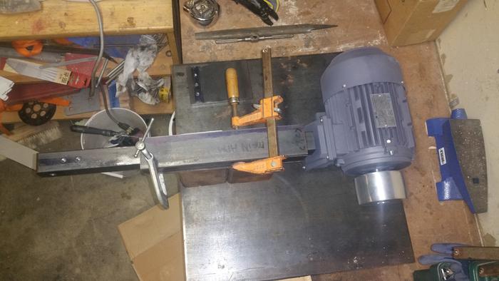
So, here are some pictures that I want to get everyones take on . I want to have a direct drive belt "drive wheel attached to motor" . Questions are these .
1. Do I have enough room between tooling arm and motor ?
2 . Will it work ? I guess dumb question ?
I have a few more pieces of metal to get cut and more drilling and tapping holes . For kicks I took a taylor's measuring tape and put it around the drive wheel and looped it around with my hand resembling 6 feet long. It looks like it will work. It is similar to a kmg design from the plans on this site . I am just not using pullys . I have a vfd that will be wired to the motor . and I would like to have a switch board on the base plate to control on , off, speed , and forward and reverse if anyone has a site for that type of an item ? I will house the vfd in its own box away from the grinder . I could use answers to questions and imput on design and such . This has been a long project as I have limited "I mean really" limited time to get it done. But its getting close . Let me know your thoughts all .
Understand that nothing is welded up yet . I will tap and bolt the motor to the plate. The tooling arm shaft will be welded , and basically all will be welded together .
David
Your going to want to move the tooling arm laterally so that the contact wheel lines up with the drive wheel without a large overhang in the contact wheel shaft.
What he said. An inch of so of free axle is ok. But don't have your drive wheel on the end of a long free axle. It will vibrate badly, and make it harder to e'g work with a tool rest.Quote:
Originally Posted by bluesman7
these are the plans I am going by , minus the pully system ...... http://straightrazorpalace.com/attac...nder-plans.pdf
yes, of course I need to make sure they wheels line up before welding it all. But in these plans , I am not sure what to buy for bolts to hold the wheel on the tooling arm or the wheel on the tension arm. I suppose I could bring the wheels to the hardware store and try out some stuff ?
Progressing well
I have changed my motor mount design a couple times as I have drawn each section up, to allow for the alignment of my drive to tracking, to swinging wheeled platen and my small wheel holder.
I have worked everything from the outside of my tool arm as it will be a fixed dimension then to the centre of belt and back to everything else.
This is the way I did my layout also. Great minds and all that.Quote:
Originally Posted by Substance
Btw... for small wheels look at skateboard wheels... especially at the ends of a platen..
My small wheels are 2", 1" & 1/2", to,small for skate wheels possibly
Most wheels are around 2", there are specialised ones of about 3"...
Yeh most standard platen wheels are 2"
so I am back at it . I have been busy building stave drum shells , but looking at my motor and vfd sitting there , I cant just let it go to waste. and now I have an electrician buddy who will wire the vfd to the motor. So, thus a couple more parts to get machined and I will have a friend weld it all together. just to recap. I have a 2hp motor , vfd, 2 contact wheel, 6 inch contact wheel, drive wheel, tracking wheel, platen wheels , all the steel but the frame . I just need a couple of parts milled and then weld it all together . I will post pics as I progress. hopefully before to many more weeks go by.
D
So, tooling arms almost done . my buddy picks up my motor and vfd tomorrow to wire . I still have to figure out the flat platen hold spacing and plate size but its progressing . I need to take pics once the steel is back from the machinist
So, i am thinking to save space lengthwise to put in 4 bolt flange bearings , a keyed shaft and pulley like the KMG grinders . It would help not make the grinder so long , putting the motor more front and left of tooling arm. I was contemplating doing all the tapping and drilling myself but i may let the machinist do it . I don't want to be bothered . I have to much else to do .I am looking at flat platen also . Maybe i am over thinking it all . I am so used to measuring a ton of times , drill once.
Ok, so , steel back from the machinist . now to get bolts and whatnot , weld pieces together but first some questions. Does anyone know or can send me a link of what compression spring to get for my KMG clone grinder . The build is similar to the PDF on this site ? I was thinking a 1 inch wide by like 6 inch long ? and I guess something fairly strong ?
Die Springs | MSCDirect.comQuote:
Originally Posted by drmccubx
These are what I replace stock springs with on my Baders.
Attachment 227321Attachment 227322Attachment 227323Attachment 227324
ok, so here is a sample of progress on my grinder , years after starting. one pic of tooling arm, one of tracking assembly, one of work rest , one of flat platen . All are "in progress" . Tooling arm has to be welded to uprights , platen needs more holes drilled and platen welded on, tracking assembly needs to be welded to tension support . Today i go and get Bolts to hold on the wheels and other parts .
I'd get some shoes too, while I was out. :)Quote:
Originally Posted by drmccubx
Metal slivers suck..
Nice work so far, getting some ideas for an upgrade watching this thread unfold.
:tu
yeah, running up and down stairs to work a little here and there makes putting shoes on troublesome . But , alas , i should wear shoes. :) So, i got some bolts , lock washers , lock nuts . Work rest looks great . Now waiting on steel from local welder for the uprights. Though i do have some 3/8th's inch thick steel i could use . I asked the welder for 3/4 inch thick . Would it make a difference ? Whats everyones take . 3/8ths or 3/4 for uprights to hold tooling arm ? Very few steps to go . Oh , another question . Do people use threaded rod for the wheel axles ? or get long bolts and washers ? Hopefully next week it gets welded up
http://images.tapatalk-cdn.com/16/02...6ce87d96ec.jpg so here is the tool rest done. You get the idea
http://images.tapatalk-cdn.com/16/02...6ff8b7aa5a.jpg here is the vfd and motor. It's getting there
http://images.tapatalk-cdn.com/16/02...101eea9df4.jpg slots made for adjusting platen.
So I guess my question about a spring is what length to get ? Thanks mike for the suggestion. I just don't know if the one you suggest will do . its 3 inch length is short , no ? for a KMG clone that is . I just don't want to guy and have to return . I was told it should compress 1 inch per 30lbs ?
looking good & progressing well mate
also good to see someone who wears the same shed safety shoes as me LOL
I use a valve spring along with the spring seats on a KMG clone. The spring is much stiffer than 30lbs per inch. I don't think that the rate is very important, though it seems to me that a stiffer spring makes the design easier because the length does not change very much over a range of tensions. I would guess that I use the grinder with about 30-50lbs of tension in the spring.Quote:
Originally Posted by drmccubx
Attachment 227735