Results 1 to 10 of 16
 4Likes
 LinkBack URL
 About LinkBacks
Hybrid View
-
11-09-2017, 12:04 AM #1Member

- Join Date
- Mar 2010
- Location
- Auckland New Zealand
- Posts
- 43
Thanked: 7 Any Electrical Engineers out there who can explain something?
Hi Guys,
All was well with my grinder and the world until the other day when I heard a 'BANG' as I was grinding a blade.
I suspect that metal dust had got into the VSD (Controller) and shorted it. Sure enough when I disconnected everything and looked inside there were come blackened components.
Now the fun starts in trying to source a replacement.
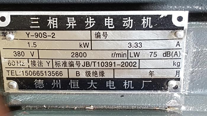
My motor is 380 Volt 3 Phase (please see plate below)
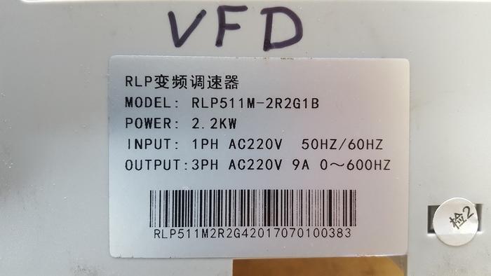
My current VSD label states:
240 Volt Single Phase Input (Standard New Zealand and UK Power)
240 Volt 3 Phase output
Label Below:
If my motor is 380 Volt, how did this work - or is the 3 Phase the key - the VSD was working fine until the dust issue.
Do I not need a 240 Volt Single Phase input/380 Volt 3 Phase Output VSD?
Some suppliers say 240 Volt 3 phase output is fine, while others say 380 Volt 3 Phase Output.
Any advice appreciated.
-
11-09-2017, 12:17 AM #2Senior Member


- Join Date
- Oct 2010
- Location
- 50 miles west of randydance
- Posts
- 9,692
Thanked: 1354
Good question.
This is the first thing that came up in my search for an answer.
https://electronics.stackexchange.co...n-on-220-volts
 I don't understand much of that!
Good luck and I will be lurking.sharptonn likes this.
-
11-09-2017, 12:25 AM #3Member
- Join Date
- Mar 2010
- Location
- Auckland New Zealand
- Posts
- 43
Thanked: 7
Thanks for that 32t,
You would think that an IT Project Manager would have tried Google :-)
Like you, I don't really understand a lot of that article, but it seems to indicate that my VSD/VFD output of 240 Volt 3 Phase is OK.
 Originally Posted by 32t

-
11-09-2017, 02:19 AM #4Senior Member

- Join Date
- Oct 2017
- Location
- Tulsa, OK
- Posts
- 359
Thanked: 74
Many/most VFD/VSD will take single phase power and generate the third phase for 3 phase output. They can also take 3 phase power in and give 3 phase power out.
Does this answer your question?
-
11-09-2017, 02:45 AM #5Member
- Join Date
- Mar 2010
- Location
- Auckland New Zealand
- Posts
- 43
Thanked: 7
Hi Robini,
Thanks for that. It was more the fact that my current VFD has an output of 240 Volts when my motor is 380 Volts?
Originally Posted by Robini
-
11-09-2017, 02:46 AM #6Senior Member

- Join Date
- Jan 2012
- Location
- Waukesha, Wisconsin
- Posts
- 1,943
Thanked: 390
From what I remember when researching this for work, motors can (but not all) have a low and high speed connection. 220V for low and 380 for high. You just have to wire it correctly, typically there is a wiring diagram printed on the cover for the connections on the motors we use. I would buy something with the same specifications and rewire the way it was, it worked before and didn't burn your house down.
-
The Following User Says Thank You to dinnermint For This Useful Post:
onotoman (11-09-2017)
-
11-09-2017, 02:53 AM #7Senior Member
- Join Date
- Oct 2017
- Location
- Tulsa, OK
- Posts
- 359
Thanked: 74
dinnermint, you are exactly correct. All 3 phase motors I have worked with can be wired to different voltages, just pay attention to the diagram and your golden.
-
11-09-2017, 02:54 AM #8Member
- Join Date
- Mar 2010
- Location
- Auckland New Zealand
- Posts
- 43
Thanked: 7
Good point - My workshop is a wooden shed, so even more risk, but yes, it didn't burn down :-)
Originally Posted by dinnermint
-
11-11-2017, 11:10 PM #9
I'm not an electrical engineer, but I can explain the math/physics. Originally Posted by onotoman
First, electrical voltage is measured on 'interval scale' i.e. it is always relative voltage or difference between two points.
Three-phase electrical power/voltage comes with three active leads, which means that the voltage difference between each of them and the 'ground' is the same, in your case 220V. But that 220V is the peak or the amplitude, the actual voltage oscillates back and forth with a 50Hz or 60Hz frequency (i.e. switches 50 or 60 times per second).
Now, these three separate leads are also shifted in phase, so that they get to the peak voltage not at the same time but a third of the oscillation cycle from each other.
This means that even though each goes from -220V to +220V relative to the same 'ground' point, the difference between any two of them oscillates not with amplitude 220V but with (after simple trigonometry) 2*sin(60deg)*220V=380V (still at the same frequency though).
So, in short, the voltage between the ground and any of the 'live' wires goes back and fort from -220V to +220V 50 times a second, but between one 'live' wire and another live wire the voltage oscillates between -380V and +380V 50 times a second.
Most likely this is what the 380V notation on your motor means, but it's always best to consult with a professional who would know for sure.
-
The Following User Says Thank You to gugi For This Useful Post:
onotoman (11-14-2017)
-
11-12-2017, 01:36 AM #10Senior Member


- Join Date
- Jul 2014
- Location
- Denver CO
- Posts
- 4,653
Thanked: 811
Actually AC voltages are measured RMS [root mean square] so 220 volts AC will dissipate the same energy as 220 DC through the same resistance. The peak voltage of a 220 AC supply will be 1.41 times the RMS voltage or 310 volts. None of this has anything to do with the OPs question.
Induction motors are designed to operate at a given voltage at a specified frequency. The labeling on the motor does not make any sense to me as the speed is listed at 2800 and the freq. specified as 60 hz.. A 2 pole induction motor has a synchronous speed of 3600 at 60hz and with the slip at full load it is usually around 3450 or so. The same motor will run around 2800 at 50hz. The VFD label doesn't really make sense either as the voltage should vary proportionately with the frequency. Running an induction motor at a voltage lower than specified for a given freq. will increase the slip at load and can over heat the motor by drawing too much amperage. It's possible that excess current was the cause of the failure of the VFD.
Were you loading the grinder heavily [sensing slow down] around the time of the failure?
In my mind the VFD should have a spec. in volts/hz that matches the volts/hz of the motor.Last edited by bluesman7; 11-12-2017 at 01:39 AM.


 Reply With Quote