
Results 1,531 to 1,540 of 2531
 8913Likes
Thread: 51 MG restoration.
 LinkBack URL
 About LinkBacks
Threaded View
-
03-31-2018, 09:28 PM #1Str8Faced Gent.


- Join Date
- Aug 2013
- Location
- Orangeville, Ontario
- Posts
- 8,467
- Blog Entries
- 1
Thanked: 4207 51 MG restoration.
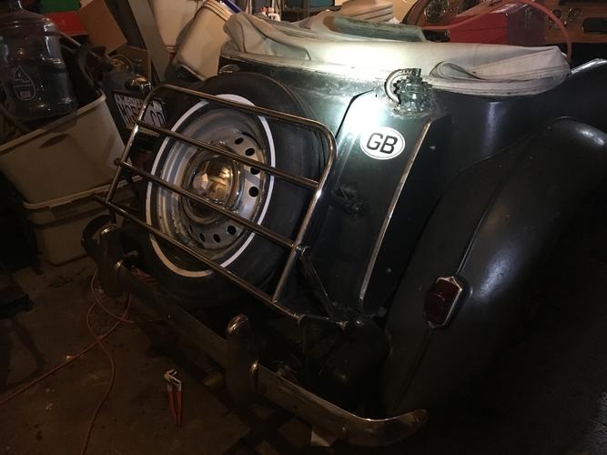
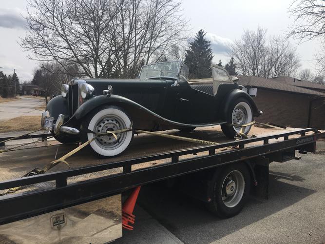
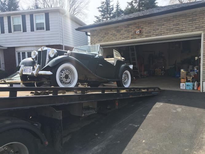
Figured I’d start a thread to avoid flooding the Classic car thread with this project.
Got her home today.
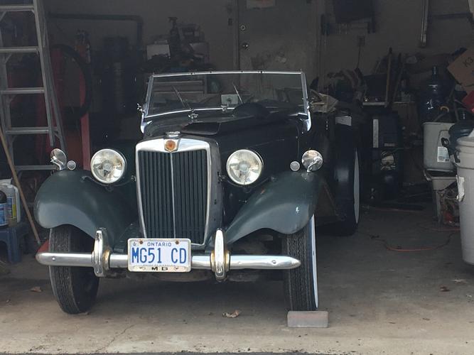
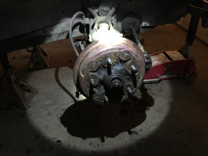
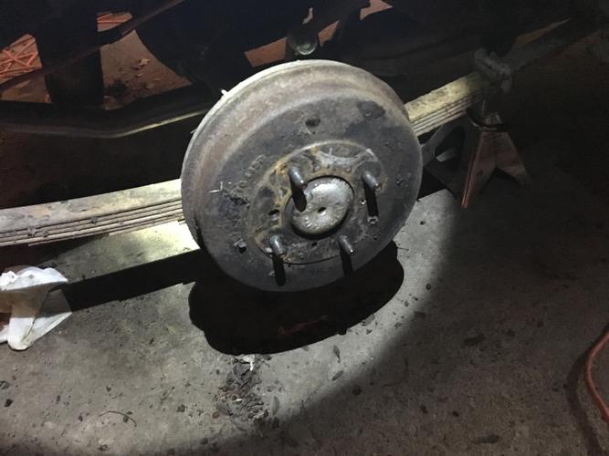
Up on jacks already, wheels off and draining the tank.
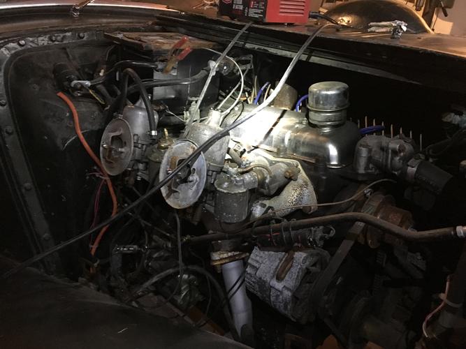
Already got the fuel pump working, bad ground. But the fuel smells like shellac so draining everything and starting fresh before I try to get her started.
Brakes come off next. Only been 20 years since my last drum brake job.
So far, all electrical checks out but brake lights and heater, which it has. Choke is seized as well. Parking brake cable barely moved so I didn’t force it.
Need better light in the garage now.
Time to buy some led strips..
Cheers."Depression is just anger,, without the enthusiasm."
Steven Wright
https://mobro.co/michaelbolton65?mc=5
-
The Following 11 Users Say Thank You to MikeB52 For This Useful Post:
cudarunner (04-01-2018), Diboll (04-01-2018), dinnermint (08-10-2018), engine46 (04-23-2020), Geezer (04-01-2018), Haroldg48 (12-19-2021), markbignosekelly (04-01-2018), MisterClean (05-08-2018), outback (04-01-2018), Phrank (03-31-2018), SemperFi (04-01-2018)


 Reply With Quote