Results 1 to 10 of 18
 20Likes
Thread: New grinder project
 LinkBack URL
 About LinkBacks
-
10-23-2014, 03:52 AM #1Tumbling down the rabbit hole...


- Join Date
- May 2011
- Location
- Calgary, AB
- Posts
- 445
Thanked: 27 New grinder project
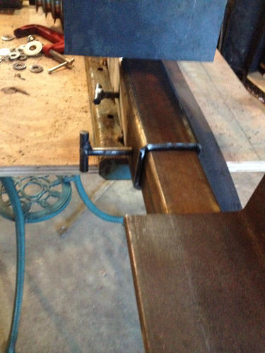
Check it out... My first tool-making project. All eyeballed so far.
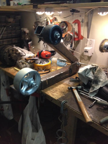
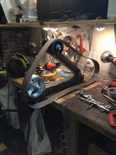
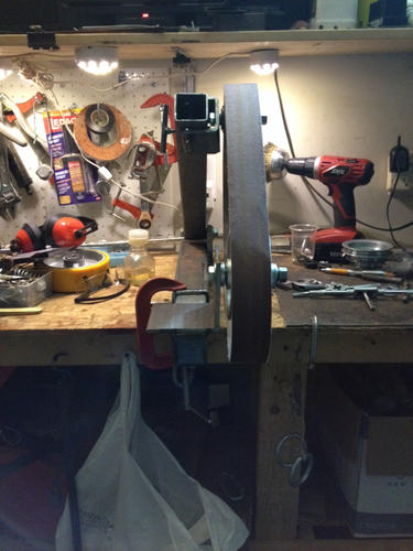
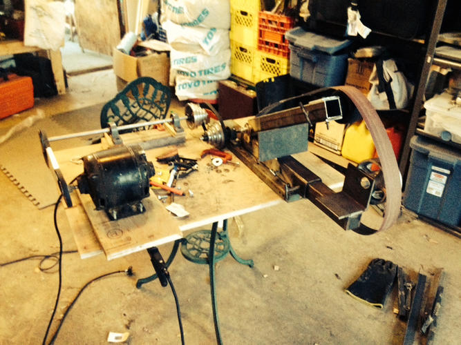
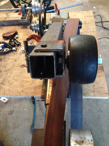
I need to finish the base and the drive wheel. It will be a pulley and belt system with 4 speeds.
-
The Following User Says Thank You to Atchbo For This Useful Post:
williamc (11-07-2014)
-
10-23-2014, 05:49 AM #2
This look solid enough. I only wonder: Those arms look fairly heavy, and the wheel is bolted on. how easy will it be to swap attachments?
skipnord likes this.Til shade is gone, til water is gone, Into the shadow with teeth bared, screaming defiance with the last breath.
To spit in Sightblinders eye on the Last Day
-
10-23-2014, 12:52 PM #3Tumbling down the rabbit hole...
- Join Date
- May 2011
- Location
- Calgary, AB
- Posts
- 445
Thanked: 27
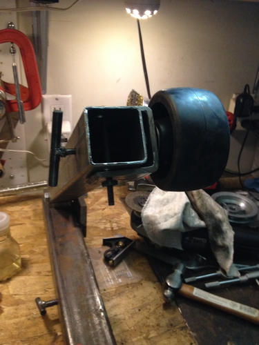
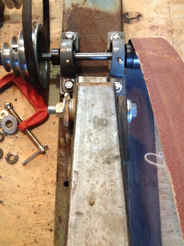
We'll have to see. The arm for the contact wheel slides in and out, held in place by two T nuts I made from 3/8" rod.
There are a few holes in that big angle piece on the tool arm but all the contact wheels will be bolted on. Easy enough to change. It was tricky to get that angle/bracket welded on at the right angle. I had to clamp a straight edge onto the wheel when bolted on to the bracket, and shim it along the length of the telescoping arm so I could see if there was any angle deviation over a distance, and then I tacked it on.
I have more steel to make another tool arm if needed, but I have a Grizzly with a platen, so I might just use this grinder for hollowing. I have a 6" caster wheel with PU tread, this 5" steel wheel, and I'm going to try to find some small contact wheels... bushings or something for <1/2" and about 1" and about 2".
I have a really coarse belt for fast removal (likely on the Griz) and a 120 orange ceramic belt and another Norton ceramic belt of some sort from knifemaker.ca.Last edited by Atchbo; 10-23-2014 at 01:03 PM.
-
The Following User Says Thank You to Atchbo For This Useful Post:
Bruno (10-23-2014)
-
10-23-2014, 04:32 PM #4
If it is for hollowing at a certain diameter, I can see the benefit there. My main 'concern' if you'd call it that, is that if you wanted to use it as a universal grinder, you'd have a lot of big heavy arms with different wheel sizes etc. Not that there is a functional problem of course, but from a practical pov it could be a bit cumbersome.
Til shade is gone, til water is gone, Into the shadow with teeth bared, screaming defiance with the last breath.
To spit in Sightblinders eye on the Last Day
-
10-23-2014, 05:12 PM #5
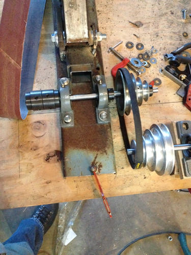
Well done! My only serious concern is the small relative size of the pivot pin. It would seem to me to be an ongoing renewal problem. There is a lot of twisting with the outboard wheel and that may cause problems.
I suggest making two arcs / quadrants of steel and weld them to each side of the base tube to stiffen the assembly. If they are about 8 inches on a side they would not interfere with any of the grinding operations.

They could also have a clamp like a fancy "C" clamp across them and the tension tube to really hold it well.
Just my thoughts,
You have about the simplest set up I have seen and it is well thought out.
Have fun!
~RichardLast edited by Geezer; 10-23-2014 at 05:27 PM.
skipnord likes this.Be yourself; everyone else is already taken.
- Oscar Wilde
-
10-23-2014, 07:12 PM #6Senior Member

- Join Date
- Apr 2014
- Location
- Bristol Uk
- Posts
- 260
Thanked: 57
Good stuff, it looks like just the job.
-
10-23-2014, 08:12 PM #7Tumbling down the rabbit hole...
- Join Date
- May 2011
- Location
- Calgary, AB
- Posts
- 445
Thanked: 27
Too much for a 1/2" bolt?
I could weld on a second side for the main pivot so it is not just the 1/2" steel plate holding the 1/2" bolt.
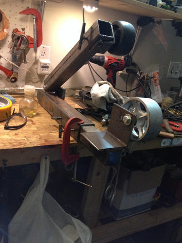
I think I will weld or bolt the whole contraption to a metal base. Might need that anyway for my belt tensioning plan for the drive shaft (4-speed pulley on one side and 2" drive wheel on the other, on pillow blocks).
-
10-23-2014, 08:14 PM #8Tumbling down the rabbit hole...
- Join Date
- May 2011
- Location
- Calgary, AB
- Posts
- 445
Thanked: 27
Or do you mean welding the tracking arm instead of having it on a pivot and spring?
-
10-23-2014, 09:42 PM #9
I meant that using the quadrants (sketched in red)or even squares of plate will reduce the twisting stress on the pivot arm bolt. It would also be a way to clamp the arm at any angle with a bar or "C"clamp.
 Originally Posted by Atchbo

Yes, a wide and long base welded to your bottom bar every two inches along it with a bead of 1 inch long on both sides would be a winner. That welding method reduces distortion.
No.Or do you mean welding the tracking arm instead of having it on a pivot and spring?
~RichardBe yourself; everyone else is already taken.
- Oscar Wilde
-
11-07-2014, 01:05 AM #10Tumbling down the rabbit hole...
- Join Date
- May 2011
- Location
- Calgary, AB
- Posts
- 445
Thanked: 27
Some progress:
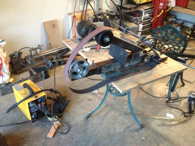
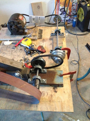
Slow going when you're me!
-
The Following 4 Users Say Thank You to Atchbo For This Useful Post:
Geezer (11-07-2014), Neil Miller (11-24-2014), spazola (11-09-2014), williamc (11-07-2014)


 Reply With Quote