
Results 31 to 40 of 50
 110Likes
 LinkBack URL
 About LinkBacks
Threaded View
-
07-19-2014, 08:32 PM #1'with that said'


- Join Date
- Aug 2010
- Location
- Walla Walla in WA State USA
- Posts
- 11,157
Thanked: 4230 Variable Speed Buffer Build/Speed Kills/Part One
I've been working on this Variable Speed Buffer Project which I now call 'My Build' for several months now.
I wanted the 'help' that a buffer can provide without the Speed or at least Speed that I could vary thus providing more control of the heat buildup.
If it wasn't for the Wisdom/Experience and Patience of a Member (who at this point in time wishes to remain Anonymous so I'll call him/Pee Wee Herman/PWH for short) and Who I am Very Proud To Call My Friend/This Variable Speed Buffer either wouldn't have happened at all or it would have been a 'Shabby Mess' and all because of my inexperience and lack of knowledge!
Time and Time Again when I would thank him for his help he would reply to the effect;
It's your build, you designed it, I have merely offered suggestions.
With my heartfelt thanks for all of the time/advice/links etc that my friend has provided to make this build what it is and how it performs I present my Homemade Variable Speed Buffer;
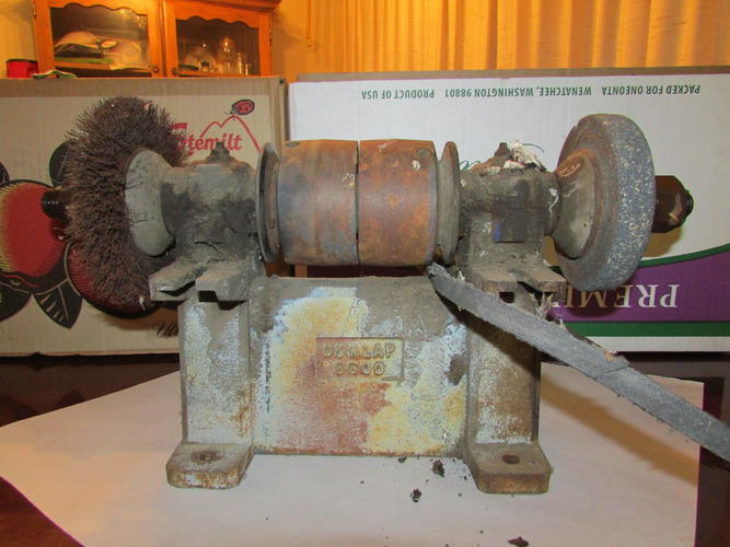
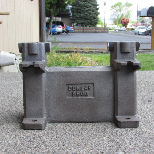
Well Ok, it's not the finished build but this is where I started. An Antique Grinder with poured Babbitt bearings. I knew that I couldn't afford to have those re-poured so I went with Pillow Block Bearings.
I wanted the cast Iron Base for Mass/Weight thus more Stability and less Vibration. Here it is after a $10 run through an acid washer at my local automotive shop.
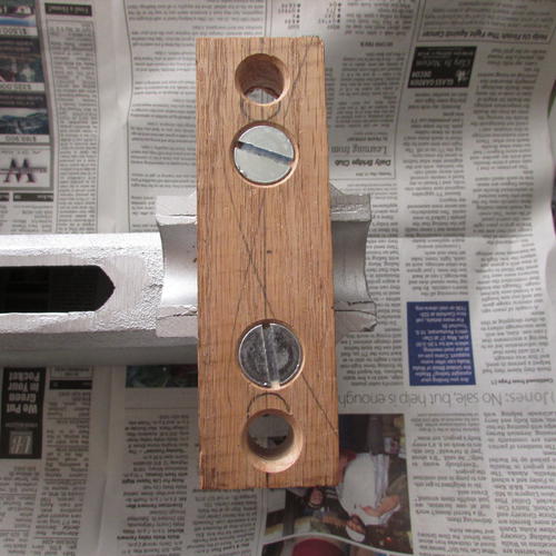
I made the adapter to mate the base with the Pillow Block Bearings out of Oak.
I purchased two step pulleys. The first one will serve as the speed reducer the second one on the final drive. Since I needed clearance not only for the first driven pulley but the others here's what my very good friend helped me make in his wood shop.
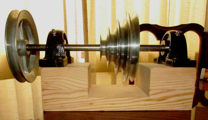
Ok so here's the basic layout.
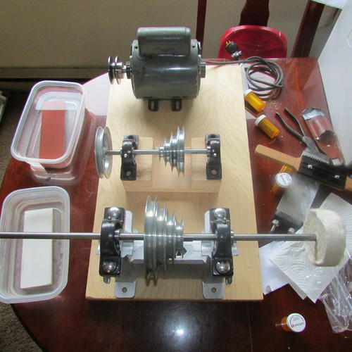
Courtesy of PWH/Here's how the speeds should work. The attached link is a Wonderful Tool. You plug in the motor speed, the driver pulley size, the driven pulley size and the distance between the shafts and it not only gives you the RPM of the driven shaft but what size belt you will need.
The motor is a 1725 RPM 3/4 HP that I've had laying around for years. The Driver Pulley on the motor is 2". The Driven Pulley on the Speed Reducer is 5".
Using the online calculator that PWH supplied the shaft for the speed reducer should be turning at 690 RPM.
Then the 2" to the 6" should be 230 RPM.
The 3" to the 5" should be 414 RPM.
The 4" to 4" should be 690 RPM
The 5" to 3" should be 1150 RPM.
I can also 'play' with the pulleys on the motor and the first driven pulley to change either faster or slower.
Here's the link to the online calculator:
Pulley, Diameter and Belt Size CalculatorOur house is as Neil left it- an Aladdins cave of 'stuff'.
Kim X
-


 Reply With Quote