Results 1 to 10 of 50
Hybrid View
-
07-19-2014, 08:32 PM #1
 Variable Speed Buffer Build/Speed Kills/Part One
I've been working on this Variable Speed Buffer Project which I now call 'My Build' for several months now.
I wanted the 'help' that a buffer can provide without the Speed or at least Speed that I could vary thus providing more control of the heat buildup.
If it wasn't for the Wisdom/Experience and Patience of a Member (who at this point in time wishes to remain Anonymous so I'll call him/Pee Wee Herman/PWH for short) and Who I am Very Proud To Call My Friend/This Variable Speed Buffer either wouldn't have happened at all or it would have been a 'Shabby Mess' and all because of my inexperience and lack of knowledge!
Time and Time Again when I would thank him for his help he would reply to the effect;
It's your build, you designed it, I have merely offered suggestions.
With my heartfelt thanks for all of the time/advice/links etc that my friend has provided to make this build what it is and how it performs I present my Homemade Variable Speed Buffer;
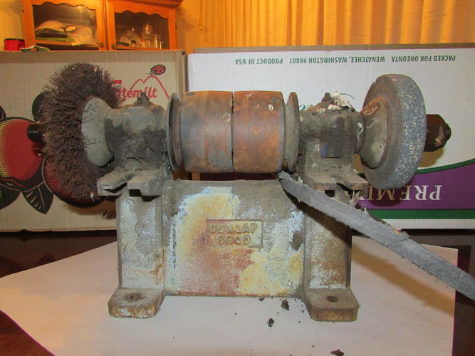
Well Ok, it's not the finished build but this is where I started. An Antique Grinder with poured Babbitt bearings. I knew that I couldn't afford to have those re-poured so I went with Pillow Block Bearings.
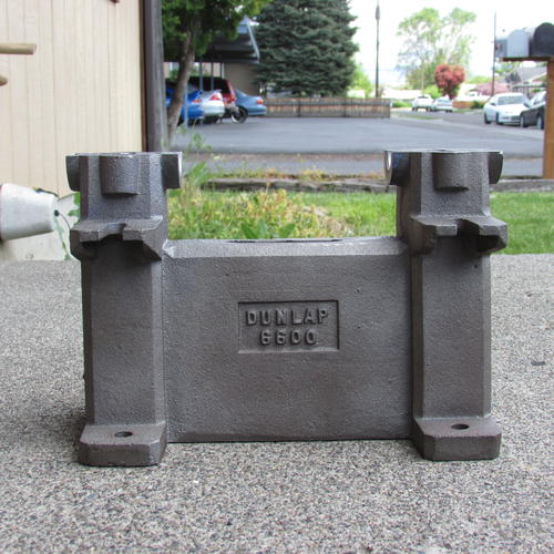
I wanted the cast Iron Base for Mass/Weight thus more Stability and less Vibration. Here it is after a $10 run through an acid washer at my local automotive shop.
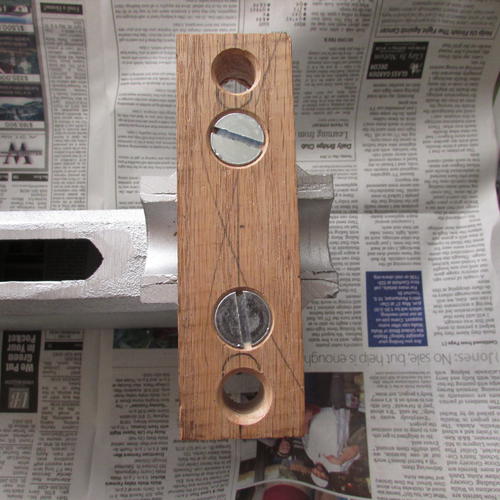
I made the adapter to mate the base with the Pillow Block Bearings out of Oak.
I purchased two step pulleys. The first one will serve as the speed reducer the second one on the final drive. Since I needed clearance not only for the first driven pulley but the others here's what my very good friend helped me make in his wood shop.
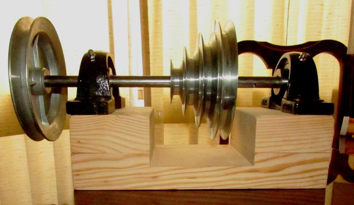
Ok so here's the basic layout.
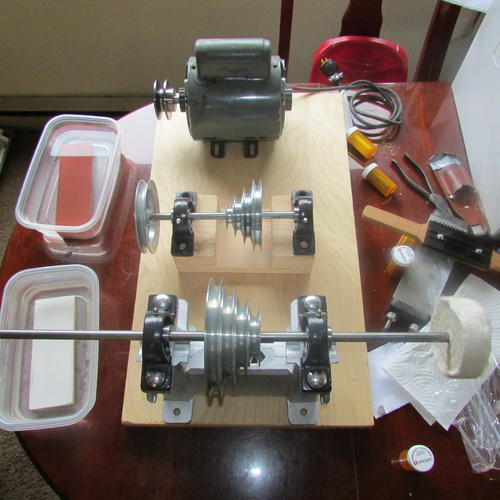
Courtesy of PWH/Here's how the speeds should work. The attached link is a Wonderful Tool. You plug in the motor speed, the driver pulley size, the driven pulley size and the distance between the shafts and it not only gives you the RPM of the driven shaft but what size belt you will need.
The motor is a 1725 RPM 3/4 HP that I've had laying around for years. The Driver Pulley on the motor is 2". The Driven Pulley on the Speed Reducer is 5".
Using the online calculator that PWH supplied the shaft for the speed reducer should be turning at 690 RPM.
Then the 2" to the 6" should be 230 RPM.
The 3" to the 5" should be 414 RPM.
The 4" to 4" should be 690 RPM
The 5" to 3" should be 1150 RPM.
I can also 'play' with the pulleys on the motor and the first driven pulley to change either faster or slower.
Here's the link to the online calculator:
Pulley, Diameter and Belt Size CalculatorOur house is as Neil left it- an Aladdins cave of 'stuff'.
Kim X
-
-
07-19-2014, 08:44 PM #2
 Variable Speed Buffer Build/Speed Kills/Part Two
Here's some pictures of the Build. I may make some drop over guards to cover the belts and I have leftover laminate to cover the plywood if I do so.
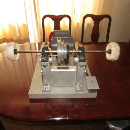
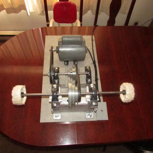
(No the belt is not out of alignment! It's just the camera angle.)
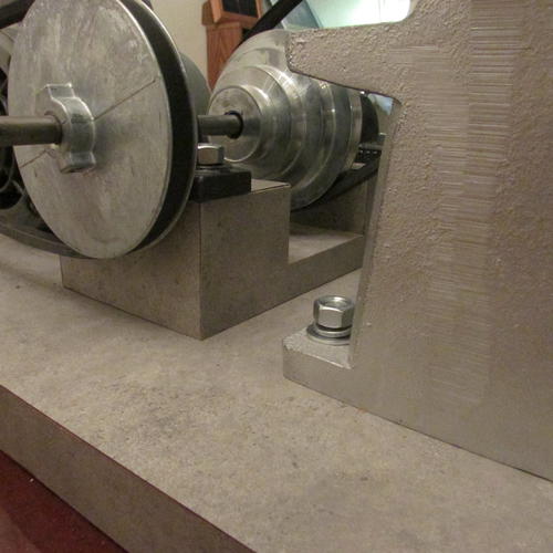
The 4" spiral sewn buffer pads are held in place with these:
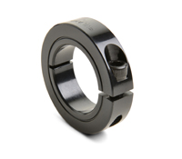
I'm looking forward to trying it out. I would call it 'semi' portable as it has to weigh about 100 LBS. I will more than likely have it on top of my vintage table saw in my very cluttered garage for now. My wood working friend and I are going to keep our eyes out for a used bathroom vanity to make a base for it. That should provide a good height to work with and have drawers etc for storing compounds/buffer wheels etc.
I purchased the pillow block bearings online from; The Big Bearing Store.
http://www.thebigbearingstore.com/
I highly recommend them. When I ordered the bearings I accidentally hit 3 instead of 4 and didn't notice until I got an email saying that my order would be shipped soon. I immediately contacted their customer service told them of my mistake and asked if it was too late to correct it.
Anita wrote back saying that she would hold the order and all I needed to do was use the PayPal to purchase the extra bearing and that there would be no extra charge for shipping.
I thanked her and told her a little about the build, she asked to be kept up to date and I have.
This buffer runs smooth as silk. The old motor has a bit of noise to it but everything else is sooooo quiet!
Well That's That I hope all will enjoy my Build. Our house is as Neil left it- an Aladdins cave of 'stuff'.
Kim X
-
The Following 11 Users Say Thank You to cudarunner For This Useful Post:
bongo (07-31-2014), Geezer (07-20-2014), MattCB (07-19-2014), Neil Miller (07-20-2014), Prahston (09-25-2014), Raol (08-12-2014), ScottGoodman (12-05-2014), sharptonn (07-20-2014), Siguy (07-22-2014), spazola (07-19-2014), walleyeman (07-20-2014)
-
07-19-2014, 09:26 PM #3

Very well done! That looks like a well executed project. Looking forward to seeing what you can do with it!
The older I get the more I realize how little I actually know.
-
The Following User Says Thank You to MattCB For This Useful Post:
cudarunner (07-20-2014)
-
07-19-2014, 11:38 PM #4

Thanks Matt, I am looking forward to seeing what this Buffer will do!
I can't tell you how many times this build has been assembled, then disassembled then reassembled etc!
My next day off is Tuesday so I'll try to play with it then. I don't have any razors that would need a coarse grit but I have a couple that I might try with the 'finishing' compounds on.
I Definitely Will Not Use It On Other People's Blades until I know how it works!Our house is as Neil left it- an Aladdins cave of 'stuff'.
Kim X
-
07-20-2014, 03:01 AM #5

I sure do like your setup it looks well built and thought out. I am a fan of cone pulleys and pillow blocks, that is my kind of engineering.
Charlie
-
The Following User Says Thank You to spazola For This Useful Post:
cudarunner (07-20-2014)
-
07-20-2014, 03:09 AM #6

You done good! That is a really workmanlike solution to the problem of correct speed and simple changeovers.
Have Fun!
~RichardBe yourself; everyone else is already taken.
- Oscar Wilde
-
The Following User Says Thank You to Geezer For This Useful Post:
cudarunner (07-20-2014)
-
07-22-2014, 12:47 AM #7

Here's an update on the variable speed buffer.
I've been playing with it and I believe that I'd slowed things down a bit too much
So I removed the 2" driver pulley from the motor and replaced it with a cast iron 3" that I had originally intended to use. The slots in the base of the motor had plenty of movement to accommodate the larger pulley and still use the 28" belt. I think that I now have it where I want it.
Here's what I posted about the original setup and the speeds.
Courtesy of PWH/Here's how the speeds should work. The attached link is a Wonderful Tool. You plug in the motor speed, the driver pulley size, the driven pulley size and the distance between the shafts and it not only gives you the RPM of the driven shaft but what size belt you will need.
The motor is a 1725 RPM 3/4 HP that I've had laying around for years. The Driver Pulley on the motor is 2". The Driven Pulley on the Speed Reducer is 5".
Using the online calculator that PWH supplied the shaft for the speed reducer should be turning at 690 RPM.
Then the 2" to the 6" should be 230 RPM.
The 3" to the 5" should be 414 RPM.
The 4" to 4" should be 690 RPM
The 5" to 3" should be 1150 RPM.
I can also 'play' with the pulleys on the motor and the first driven pulley to change either faster or slower.
Here's the new speeds:
The speed reducer should be turning at 1035 RPM.
The 2" to 6" should be 345 RPM
The 3" to 5" should be 621 RPM
The 4" to 4" should be 1035 RPM
The 5" to 3" should be 1725 RPM
I'll play some more but so far I think that it's going to work very well.
Thanks for looking. Our house is as Neil left it- an Aladdins cave of 'stuff'.
Kim X
-
The Following 3 Users Say Thank You to cudarunner For This Useful Post:
engine46 (07-31-2014), spazola (07-22-2014), walleyeman (07-22-2014)


 110Likes
 LinkBack URL
 About LinkBacks


 Reply With Quote

