
Results 1 to 10 of 17
 29Likes
Thread: 2x72 Grinder concept
 LinkBack URL
 About LinkBacks
Hybrid View
-
04-16-2019, 12:31 AM #1Senior Member


- Join Date
- Jan 2015
- Location
- Pinole, ca
- Posts
- 1,526
Thanked: 339 2x72 Grinder concept
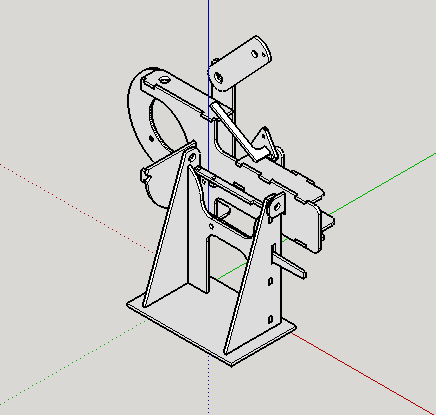
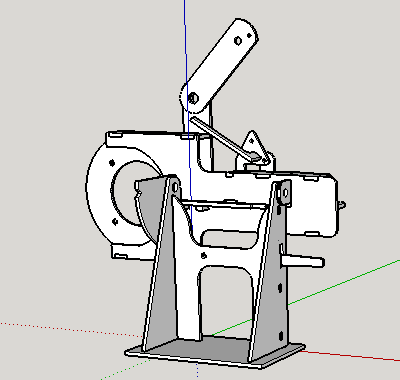
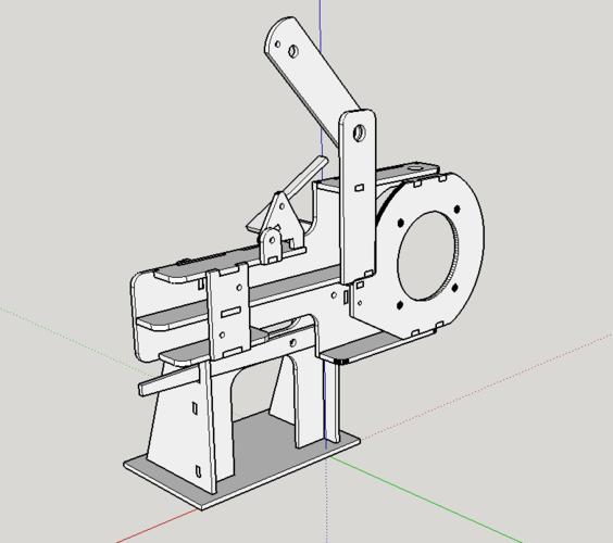
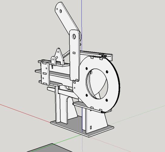
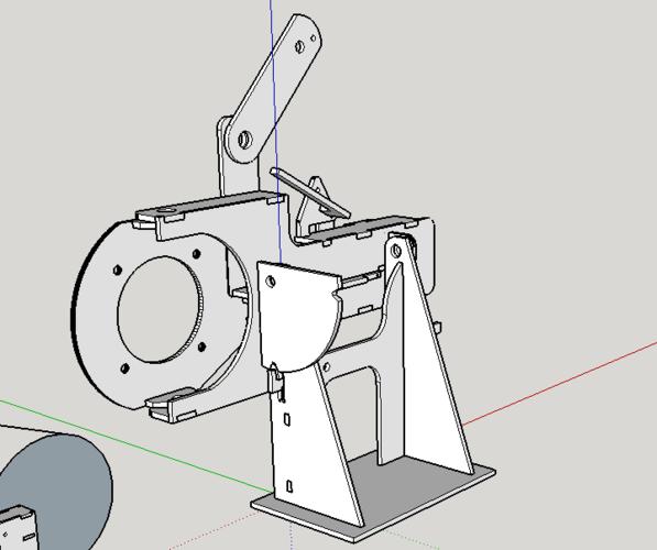
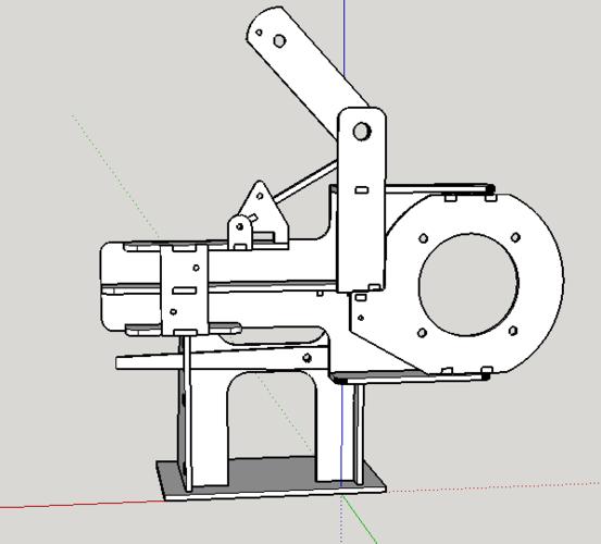
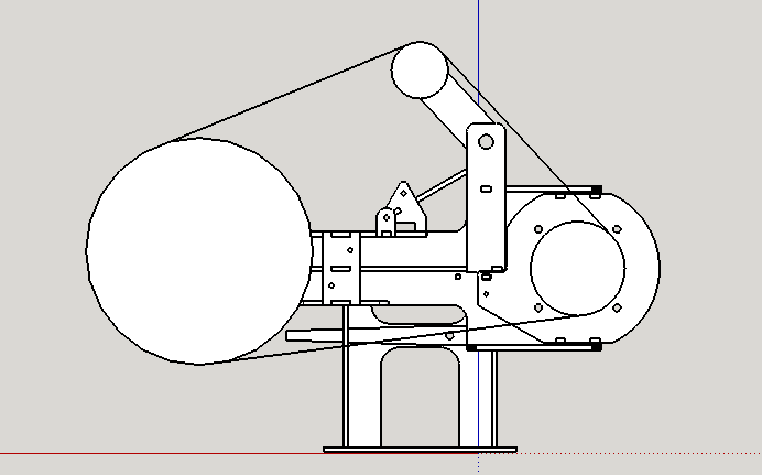
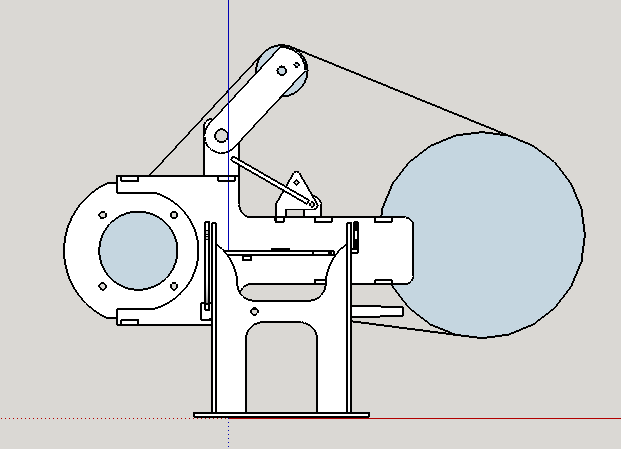
Been working on this design for last couple weeks. I'm hoping for some opinions on the design, like if theres anything I should change, design flaws, etc... You'll have to use some imaginative license as I didn't draw any tool arms or wheels, besides the mock up to make sure the geometry would work. The mock up wheels are 12" contact, 5" drive, 3" idler.
-
The Following 2 Users Say Thank You to jfk742 For This Useful Post:
sharptonn (04-16-2019), Voidmonster (04-16-2019)
-
04-16-2019, 12:34 AM #2Captain ARAD.


- Join Date
- May 2011
- Location
- Pacifica, CA
- Posts
- 2,474
Thanked: 2227
I'm looking forward to what folks with experience think. This looks great to me, and it really nicely leverages cutting with the waterjet (soon may it be available again!) Originally Posted by jfk742
 Geezer likes this.-Zak Jarvis. Writer. Artist. Bon vivant.
-
04-16-2019, 01:43 AM #3Senior Member


- Join Date
- Jul 2014
- Location
- Denver CO
- Posts
- 4,653
Thanked: 811
Looks good John. I'm not undderstanding what the triangle and lever arm above the tool arm receiver is. Does this lock the tool arm?
sharptonn likes this.
-
04-16-2019, 02:48 AM #4Senior Member
- Join Date
- Jan 2015
- Location
- Pinole, ca
- Posts
- 1,526
Thanked: 339
I was thinking about doing the whole ratcheting deal from the TW but got to thinking, I have a couple of 40lb gas struts laying around so I made a cam. I figure I can set tension by pulling the tooling arm tight against the belt then pushing it back a little then use the cam by just flipping the arm on it. Once I have the distance set for a wheel I’m thinking belt changes will just be a matter of letting off the cam then switching belts and flipping the cam back over.
The cam is in the tensioned position in the renderings, pull that arm forward for off.sharptonn likes this.
-
04-16-2019, 01:53 PM #5Senior Member
- Join Date
- Jul 2014
- Location
- Denver CO
- Posts
- 4,653
Thanked: 811
I'm still not seeing it, but that's OK. 1/4" does seem a bit flimsy for the idler arm. Originally Posted by jfk742
The ratchet deal on the TW grinder allowed the tool arm to be set at a given distance independent of wheel sizes, but I didn't see the advantage of it.
I see that you are tracking at the drive wheel. If you could get the pivots out closer to center of the drive wheel it will effect your tension less as you track. I don't know how important that will be in use though.sharptonn and Voidmonster like this.
-
04-16-2019, 07:09 PM #6Senior Member
- Join Date
- Jan 2015
- Location
- Pinole, ca
- Posts
- 1,526
Thanked: 339
Good thinking, I’ll play around some and see what I can do, maybe I’ll revisit the ratcheting thing or at least try and get some more adjustability so that small wheels are sticking out a crazy amount.
sharptonn and Voidmonster like this.
-
04-16-2019, 02:52 AM #7Senior Member
- Join Date
- Jan 2015
- Location
- Pinole, ca
- Posts
- 1,526
Thanked: 339
Victor, do you think I should be concerned about the idler arm being too flimsy? Im thinking cutting everything from 1/4 hot rolled ASTM-36
-
04-16-2019, 09:55 PM #8Senior Member

- Join Date
- Oct 2010
- Location
- 50 miles west of randydance
- Posts
- 9,690
Thanked: 1354
The whole drawing gives me the impression of being flimsy but I think that is my first impression. Originally Posted by jfk742
The 3 pivot points are what I see as a possible issue. 1/4 wide isn't that large of a bearing surface.
What if for example you made 2 idler arms of the dimensions that you show and put one on each side of the upright? That would roughly give you 3/4" or more of thickness to prevent twisting of the shafts or pins.
I think I could word this much better but do you see my thoughts?jfk742 likes this.


 Reply With Quote