
Results 1 to 10 of 22
 12Likes
Thread: Help.. Electric motor wiring.
 LinkBack URL
 About LinkBacks
-
04-13-2013, 12:06 AM #1Senior Member


- Join Date
- Mar 2013
- Location
- N.E. PA
- Posts
- 289
Thanked: 20 Help.. Electric motor wiring.
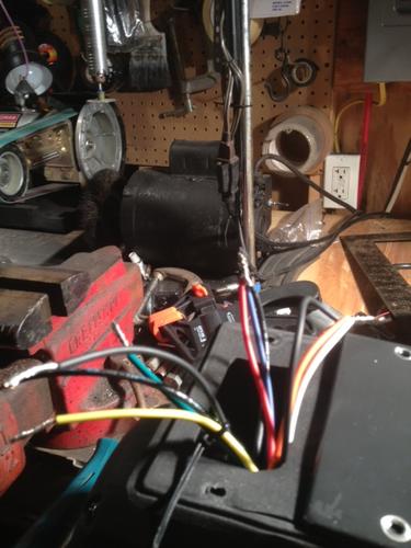
Got a brand new Dayton 1.5hp motor. It has no wiring instructions. Motor has three sets of wires.
First set is "red, blue, and black" they were already twisted together but no wire cap on them. Second set
is "black, orange, and white" they were also twisted together with no wire cap. Then there were four
other wires that were not connected to anything. One is yellow, one is green, and two are black. but one
black wire has writing on it.
-
04-13-2013, 12:09 AM #2Senior Member


- Join Date
- Feb 2008
- Posts
- 32,564
Thanked: 11044
Have you gone to Dayton's website to see if they have any online wiring instructions ? Just a thought. I can't help you myself.
-
04-13-2013, 12:10 AM #3Senior Member
- Join Date
- Mar 2013
- Location
- N.E. PA
- Posts
- 289
Thanked: 20
I'll try now.
-
04-13-2013, 12:13 AM #4Senior Member
- Join Date
- Mar 2013
- Location
- N.E. PA
- Posts
- 289
Thanked: 20
I seen images that may have a diagram on the motors label I'll have to check. But I'm no electrician, thats for sure...
-
04-13-2013, 12:34 AM #5'tis but a scratch!

- Join Date
- Oct 2010
- Location
- Durango, Colorado
- Posts
- 2,080
- Blog Entries
- 2
Thanked: 443
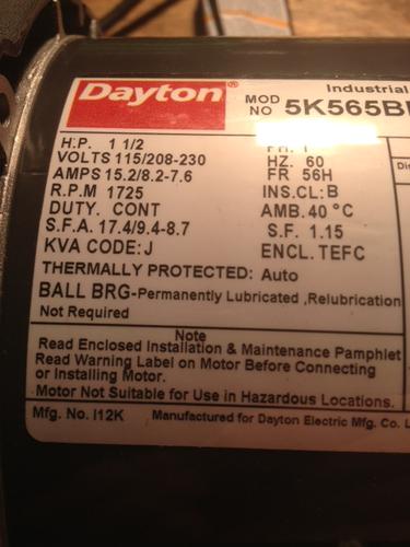
The motor can run at one of two voltages--110 or 220--and you connect some of the wires internally (that is, not to the supply power) to connect the appropriate coils. I am an electrician, and have hooked up such motors. Are there numbers printed on the wires? What voltage will you use it at? If there's a plate on the motor, put up a photo of it and I may be able to tell how to hook it all up. I'll look at their website too and see if the info is there.
Best wishes"These aren't the droids you're looking for." "These aren't the droids we're looking for." "He can go about his business." "You can go about your business."
-
The Following User Says Thank You to roughkype For This Useful Post:
officerdread (04-13-2013)
-
04-13-2013, 12:49 AM #6'tis but a scratch!
- Join Date
- Oct 2010
- Location
- Durango, Colorado
- Posts
- 2,080
- Blog Entries
- 2
Thanked: 443
It looks like some of the wires are bundled with zip ties--I think those will be your supply power. The twisted ones are probably set up for lower voltage, but that's not certain. Dayton makes dozens of motors; I can't tell you any more about yours without the nameplate info.
Most industrial settings will run the motor at higher voltage, but you don't get any more speed or power that way. At higher voltage you draw less current to do the same amount of work, so your supply wires don't heat up as much. That means that at higher voltage you can run smaller conductors to supply power to the motor. This saves money in the building's initial construction, especially if the motor is very distant from its supply panel.
From the nameplate info I can tell you what size circuit breaker you should have for the circuit that supplies this.Last edited by roughkype; 04-13-2013 at 12:57 AM.
"These aren't the droids you're looking for." "These aren't the droids we're looking for." "He can go about his business." "You can go about your business."
-
The Following User Says Thank You to roughkype For This Useful Post:
officerdread (04-13-2013)
-
04-13-2013, 12:18 PM #7Senior Member
- Join Date
- Mar 2013
- Location
- N.E. PA
- Posts
- 289
Thanked: 20
I would appreciate any help you might be able to give me. Seeing you are an electrician I'm sure this will be no problem for you to steer me in the right direction. As for the wire tie I put that on there to pull together the four loose wires and keep them separate from the rest. The others were twisted together in groups as I stated earlier.Last edited by officerdread; 04-13-2013 at 02:37 PM.
-
04-13-2013, 04:01 PM #8Senior Member
- Join Date
- Mar 2011
- Location
- Corcoran, Minnesota
- Posts
- 665
Thanked: 170
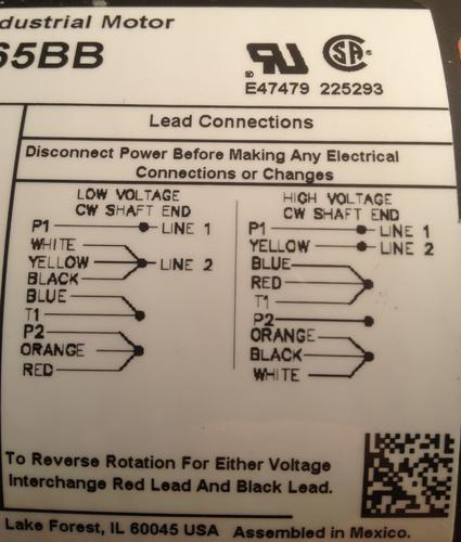
I'd wait for roughkype to confirm, but it looks like you have all the info you need in the lead connection chart in your photo. Line 1 and 2 is your input power. P1 is probably (?) the white input. Check to see what rotatational direction you want - what is pictured is for clockwise, looking at the output shaft. P1, P2 and T1 is probably printed on the appropriate wire.
-
04-13-2013, 05:31 PM #9'tis but a scratch!
- Join Date
- Oct 2010
- Location
- Durango, Colorado
- Posts
- 2,080
- Blog Entries
- 2
Thanked: 443
First, your motor has a built-in capacitor, which may hold a charge. Short out all the wires across a screwdriver or something to be sure there's nothing there that'd otherwise short out across your body. Also, never hold one bare wire in one hand then touch another bare wire with your other hand... because if there is current to flow between them, it'll flow across your heart. Put one hand in your pocket while handling wires, and stand on a dry rubber mat if possible.
It looks like your motor is currently wired for the higher voltage (208 to 230 volts), so if you're using a regular (110-115) outlet you'll need to reconnect the factory wiring. At least three of the wires will have writing on them, but you may need a magnifying glass to read it: P1, P2, and T1. T1 will be the black that is currently twisted with the red and blue. P1 and P2 will be in the four loose wires--they'll probably be the ones with black insulation. As you ID them, write the IDs on white tape and flag them to keep it easier to read.
So, starting with wires that will just be bundled back into the peckerhead (that, for some reason, is what we call the box with all the wires in it--and you may wonder, as we often do, why they installed such a damn tiny one onto the motor), here's what you'll do after you've labelled and untwisted the wires:
Nut together Red, Orange, and P2, tape the nut, and push them into the peckerhead. Do the same with Blue and T1.
Twist together the motor's White, Yellow, and unlabelled Black and leave them out of the peckerhead while you bring in your power supply cord (which should be 12 AWG).
Your power cord will have a black, a white, and a green wire. Nut together power cord green to motor green (always do the green ones first; just a good habit), then power cord white to the motor's white/yellow/black triad, then power cord black to motor P1.
If you're building your power cord from scratch, make sure that the black wire is attached under the plug's brass screw, the white is under the silver screw, and the green is under the green screw.
To test the wiring, find an outlet that is in view of your breaker panel. Bolt at least one corner of the motor to a plank, so it doesn't roll away, and turn off the breaker to the test outlet (hopefully this is a 20-amp breaker). Make sure that circuit is dead, then plug in the motor, then, with your head turned away from the motor, flip the breaker. You turn your head away so that if there's a big spark it won't blind you.
If the breaker doesn't trip, check the motor rotation. If you need to reverse it, unplug the motor and swap the Red wire from its triad in the peckerhead with the black wire that is currently nutted, along with motor yellow and motor white, to your incoming white. Nut everything back together, wrap the nut/wire junctions with electrical tape (3M Super 33 is what I'd use for this), and retest.
Hope this clears it up. Post here or PM me if you have any more questions. Best wishes and BE SAFE. Of course, never work on something that's plugged in."These aren't the droids you're looking for." "These aren't the droids we're looking for." "He can go about his business." "You can go about your business."
-
The Following 2 Users Say Thank You to roughkype For This Useful Post:
officerdread (04-13-2013), skipnord (04-13-2013)
-
04-13-2013, 07:16 PM #10Senior Member
- Join Date
- Mar 2011
- Location
- Corcoran, Minnesota
- Posts
- 665
Thanked: 170
Thanks for this excellent and thorough response, roughkype, particularly for all the safety suggestions. I will save your post for future reference, in case I ever have a similar issue myself.


 Reply With Quote