Results 51 to 60 of 90
 59Likes
Thread: Hoping to build a grinder.
 LinkBack URL
 About LinkBacks
-
04-25-2015, 12:22 AM #51Senior Member

- Join Date
- Dec 2013
- Posts
- 152
Thanked: 5
progress. well, next step is scribe out the final lines that need to be cut . and mark where the holes that will be tapped are going to be . my cousin has a friend who works at a machine shop and volunteered to do the rest of the cutting, tapping and dying and what not , so that's awesome. tomorrow at some point I mark out all the metal with detailed explanation's of what I want done. then send it to my nephew who will give it to his bud then I wait. when I get it back , I weld it all together. meanwhile I buy handles for arm and tracking and so on. cant wait .
Substance likes this.
-
06-28-2015, 02:32 PM #52Senior Member
- Join Date
- Dec 2013
- Posts
- 152
Thanked: 5
Ok, so an update with questions. I have the motor, vfd, metal mostly cut , just a couple cuts remaining. what I need to know is this . what size compression spring ? my build will be much like a KMG grinder. "spring under tension arm. Hoping to make progress within the next week.
-
06-28-2015, 03:13 PM #53
Nothing too flimsy I'd say. Take a look at the KMG ones, and then pick something close.
Til shade is gone, til water is gone, Into the shadow with teeth bared, screaming defiance with the last breath.
To spit in Sightblinders eye on the Last Day
-
06-28-2015, 03:22 PM #54Senior Member


- Join Date
- Jul 2014
- Location
- Denver CO
- Posts
- 4,632
Thanked: 811
I used a valve spring along with it's end caps. The throw on the spring is very short but it is a strong spring and works perfectly. I located it very close on the arm to where the tracking pulley is located. Originally Posted by drmccubx

-
06-29-2015, 12:23 AM #55Senior Member

- Join Date
- Jun 2013
- Location
- Gladstone QLD AUSTRALIA
- Posts
- 3,245
Thanked: 804
I am going with a Gas spring strut tat I intend to hide inside a vertical tensioning post, and all the info I have founds has a general consensus of about a 15kg/33lb (150n) strut so I would assume that the spring would be a similar rating
I ordered this for mine. 12" long with 4" travel
150N Force 300 X 18mm Lift Support Shock Strut ARM GAS Spring ROD FOR CAR | eBaySaved,
to shave another day.
-
06-29-2015, 05:16 AM #56
Keep in mind that the tension in a spring is a linear function of its compression, so you'll have to some fine tuning to make sure that when you are using it, the compression is such that that is the specific tension you'll end up with.
Til shade is gone, til water is gone, Into the shadow with teeth bared, screaming defiance with the last breath.
To spit in Sightblinders eye on the Last Day
-
07-03-2015, 02:52 PM #57Senior Member
- Join Date
- Dec 2013
- Posts
- 152
Thanked: 5 my grinder build update
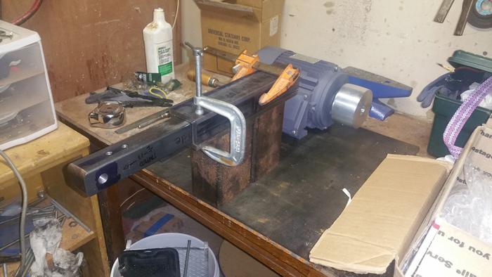
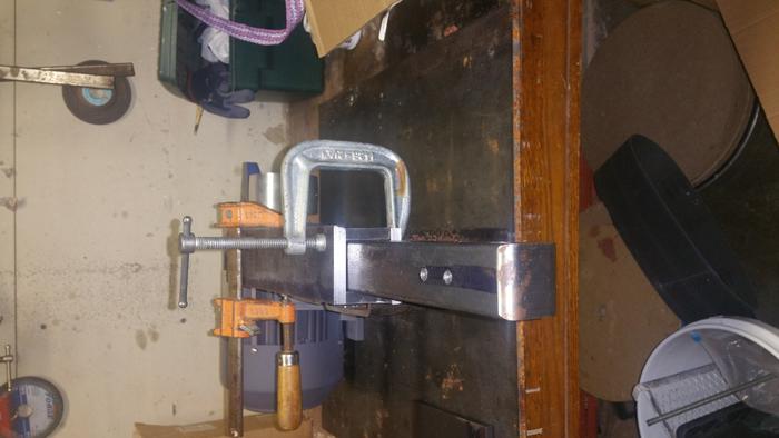
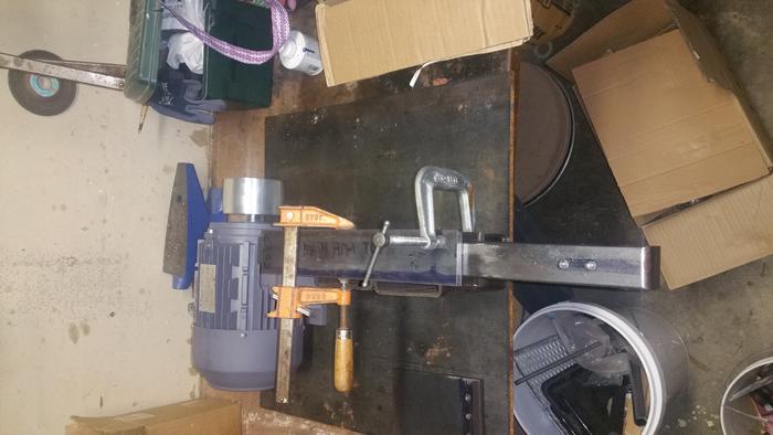
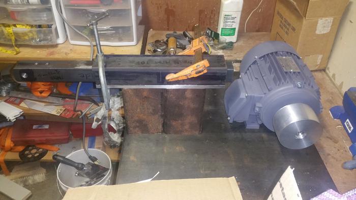
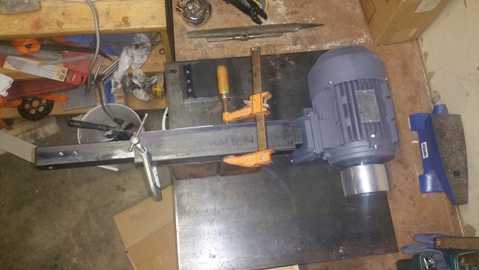
So, here are some pictures that I want to get everyones take on . I want to have a direct drive belt "drive wheel attached to motor" . Questions are these .
1. Do I have enough room between tooling arm and motor ?
2 . Will it work ? I guess dumb question ?
I have a few more pieces of metal to get cut and more drilling and tapping holes . For kicks I took a taylor's measuring tape and put it around the drive wheel and looped it around with my hand resembling 6 feet long. It looks like it will work. It is similar to a kmg design from the plans on this site . I am just not using pullys . I have a vfd that will be wired to the motor . and I would like to have a switch board on the base plate to control on , off, speed , and forward and reverse if anyone has a site for that type of an item ? I will house the vfd in its own box away from the grinder . I could use answers to questions and imput on design and such . This has been a long project as I have limited "I mean really" limited time to get it done. But its getting close . Let me know your thoughts all .
Understand that nothing is welded up yet . I will tap and bolt the motor to the plate. The tooling arm shaft will be welded , and basically all will be welded together .
David
-
07-03-2015, 03:45 PM #58Senior Member
- Join Date
- Jul 2014
- Location
- Denver CO
- Posts
- 4,632
Thanked: 811
Your going to want to move the tooling arm laterally so that the contact wheel lines up with the drive wheel without a large overhang in the contact wheel shaft.
Bruno likes this.
-
07-03-2015, 04:31 PM #59
What he said. An inch of so of free axle is ok. But don't have your drive wheel on the end of a long free axle. It will vibrate badly, and make it harder to e'g work with a tool rest. Originally Posted by bluesman7
Til shade is gone, til water is gone, Into the shadow with teeth bared, screaming defiance with the last breath.
To spit in Sightblinders eye on the Last Day
-
07-03-2015, 05:40 PM #60Senior Member
- Join Date
- Dec 2013
- Posts
- 152
Thanked: 5
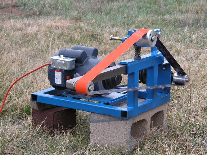
these are the plans I am going by , minus the pully system ...... http://straightrazorpalace.com/attac...nder-plans.pdf
yes, of course I need to make sure they wheels line up before welding it all. But in these plans , I am not sure what to buy for bolts to hold the wheel on the tooling arm or the wheel on the tension arm. I suppose I could bring the wheels to the hardware store and try out some stuff ?


 Reply With Quote